https://github.com/McUtty/Marlin2.0-Laser-with-M3-M4-M5-G-Code-for-Power
Kategorie: CNC
Arduino MEGA – TFT TouchScreen TP28017 – TreiberChip ILI9341
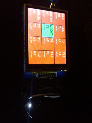
Tutorial/Beispiel für die Verwendung eines TouchScreen mit einem ARDUINO Mega
Als externes SubMenue für eine CNC Fräse o.ä. |
Bezugsquelle z.B.: https://eckstein-shop.de/32-inch-240×320-TFT-LCD-Display-mit-resistiveTouch-panel-fuer-Arduino
Arduino Library / Bibliothek hier gefunden: MCUFried TFT Display UNO y MEGA libraries.zip
ggf. auch hier – http://www.smokeandwires.co.nz/blog/a-2-4-tft-touchscreen-shield-for-arduino/
Ein Beispiel:
(Eine Push-Button-Oberfläche zum abfragen der digitalen Eingänge (InPort) mit einem PULLUP über Masse geschaltet und schalten der digitalen Ausgänge (OutPort).
[code]
// TFT size is 240×320
// Found * ILI9341 * LCD driver
// ———————————————-
// Befehle Beispiele:
// tft.reset();
// uint16_t identifier = tft.readID();
// tft.begin(identifier);
// tft.setRotation(rotation); – die Ausrichtung (0-3)
// tft.fillScreen(BLACK); – farbig füllen (in HEX)
// tft.setCursor(0, 0); – Curser Position setzen
// tft.setTextColor(WHITE); – Textfarbe (in HEX)
// tft.setTextSize(1); – Textgröße
// tft.println(“Hello World!”); – Text
// tft.drawLine(x1, y1, x2, y2, color); – Linie von x,y nach x,y in Farbe (in HEX)
// tft.drawFastHLine(0, y, w, color1); – horizontale Linie von x,y mit Länge in Farbe (in HEX)
// tft.drawFastVLine(x, 0, h, color2); – vertikale Linie von x,y mit Länge in Farbe (in HEX)
// cx = tft.width(); – TFT Breite
// cy = tft.height(); – TFT Höhe
// tft.drawRect(cx-i2, cy-i2, i, i, color); – Rechteck von Ecke x,y zur Ecke x,y in Farbe (in HEX)
// tft.fillRect(cx-i2, cy-i2, i, i, color1); – gefülltes Rechteck von Ecke x,y zur Ecke x,y in Farbe (in HEX)
// tft.fillCircle(x, y, radius, color); – gefüllter Kreis Mittelpunkt x,y mit Radius in Farbe (in HEX)
// tft.drawCircle(x, y, radius, color); – Kreis Mittelpunkt x,y mit Radius in Farbe (in HEX)
// tft.drawTriangle( – Dreieck
// cx , cy – i, // peak
// cx – i, cy + i, // bottom left
// cx + i, cy + i, // bottom right
// tft.color565(0, 0, i));
// tft.fillTriangle(cx, cy – i, cx – i, cy + i, cx + i, cy + i, – gefülltes Dreieck
// tft.color565(0, i, i));
// tft.drawRoundRect(cx-i2, cy-i2, i, i, i/8, tft.color565(i, 0, 0)); – Rechteck mit runden Ecken
// tft.fillRoundRect(cx-i2, cy-i2, i, i, i/8, tft.color565(0, i, 0)); – gefülltes Rechteck mit runden Ecken
#include <Adafruit_GFX.h> // Core graphics library
#include <Adafruit_TFTLCD.h> // Hardware-specific library
#include <TouchScreen.h>
#define LCD_CS A3 // Chip Select goes to Analog 3
#define LCD_CD A2 // Command/Data goes to Analog 2
#define LCD_WR A1 // LCD Write goes to Analog 1
#define LCD_RD A0 // LCD Read goes to Analog 0
#define LCD_RESET A4 // Can alternately just connect to Arduino’s reset pin
#define YP A3 // must be an analog pin, use “An” notation!
#define XM A2 // must be an analog pin, use “An” notation!
#define YM 9 // can be a digital pin
#define XP 8 // can be a digital pin
#define TS_MINX 180 //150
#define TS_MINY 200 //120
#define TS_MAXX 920 //920
#define TS_MAXY 940 //940
// For better pressure precision, we need to know the resistance
// between X+ and X- Use any multimeter to read it
// For the one we’re using, its 300 ohms across the X plate
TouchScreen ts = TouchScreen(XP, YP, XM, YM, 150);
#define BLACK 0x0000
#define BLUE 0x001F
#define RED 0xF800
#define GREEN 0x07E0
#define CYAN 0x07FF
#define MAGENTA 0xF81F
#define YELLOW 0xFFE0
#define WHITE 0xFFFF
Adafruit_TFTLCD tft(LCD_CS, LCD_CD, LCD_WR, LCD_RD, LCD_RESET);
#define BOXSIZE 80
#define PENRADIUS 3
#define MINPRESSURE 10
#define MAXPRESSURE 1000
#define BOX_COLORE_ON GREEN
#define BOX_COLORE_OFF RED
#define FRAME_COLORE_ON BLUE
#define FRAME_COLORE_OFF BLACK
#define TEXT_COLORE_ON BLACK
#define TEXT_COLORE_OFF WHITE
// ——————————————–
// define Title
// ——————————————–
String Title[4][3] = {
{“AIR”,”WATER”,”BRUSH”},
{“VAC”,”LIGHT”,”T3″},
{“a1″,”a2″,”a3”},
{“b1″,”b2″,”b3”}
};
// ——————————————–
// define GCode
// ——————————————–
String GCode[4][3] = {
{“M8″,”M7″,”M9”},
{“T1″,”T2″,”T3”},
{“a1″,”a2″,”a3”},
{“b1″,”b2″,”b3”}
};
// ——————————————–
// define uTitle
// ——————————————–
String uTitle[4][3] = {
{“ON/OFF”,”ON/OFF”,”ON/OFF”},
{“ON/OFF”,”ON/OFF”,”ON/OFF”}
};
// ——————————————–
// define default Status
// ——————————————–
boolean Status[4][3] = {
{0,0,0},
{0,0,0},
{0,0,0},
{0,0,0}
};
// ——————————————–
// define default InPutStatus
// ——————————————–
boolean inputStatus[4][3] = {
{1,1,1},
{1,1,1},
{1,1,1},
{1,1,1}
};
// ——————————————–
// define In Port
// ——————————————–
int inPort[4][3] = {
{52,50,48},
{46,44,42},
{40,38,36},
{34,32,30}
};
// ——————————————–
// define Out Port
// ——————————————–
int outPort[4][3] = {
{53,51,49},
{47,45,43},
{41,39,37},
{35,33,31}
};
void setup() {
//Temp 5V Ausgang:
// pinMode(22, OUTPUT);
// digitalWrite(22, 1);
uint16_t identifier = tft.readID();
Serial.begin(9600);
tft.reset();
tft.begin(identifier);
tft.setRotation(3);
InitScreen();
// Init PINs
pinMode(13, OUTPUT);
}
//——————————————–
// MAIN
//——————————————–
void loop() {
digitalWrite(13, HIGH);
TSPoint p = ts.getPoint();
digitalWrite(13, LOW);
// if sharing pins, you’ll need to fix the directions of the touchscreen pins
//pinMode(XP, OUTPUT);
pinMode(XM, OUTPUT);
pinMode(YP, OUTPUT);
//pinMode(YM, OUTPUT);
inWatcher();
if (p.z > MINPRESSURE && p.z < MAXPRESSURE) {
int Box_y;
int Box_x;
// scale from 0->1023 to tft.width
p.x = tft.height()-(map(p.x, TS_MINX, TS_MAXX, tft.height(), 0));
p.y = tft.width()-(map(p.y, TS_MINY, TS_MAXY, tft.width(), 0));
Box_x = xBox(p.x);
Box_y = yBox(p.y);
pushButton(Box_x,Box_y);
}
}
int xBox(int p_x){
int box;
if (p_x < BOXSIZE*1) {
box = 0;
}
else if (p_x < BOXSIZE*2) {
box = 1;
}
else if (p_x < BOXSIZE*3) {
box = 2;
}
return box;
}
int yBox(int p_y) {
int box;
if (p_y < BOXSIZE*1) {
box = 3; }
else if (p_y < BOXSIZE*2) {
box = 2; }
else if (p_y < BOXSIZE*3) {
box = 1; }
else if (p_y < BOXSIZE*4) {
box = 0; }
// DEBUG
// Serial.print(“P_Y = “); Serial.println(p_y);
// Serial.print(“box = “); Serial.println(box);
// Serial.print(“BOXSIZE = “); Serial.println(BOXSIZE);
return box;
}
void pushButton(int x, int y) {
switchOutput(y, x, !Status[y][x]);
delay(500);
}
void InitScreen() {
// ——————————————–
// InitScreen
// ——————————————–
tft.fillScreen(BLACK);
for (int y=0; y<4; y++)
{
for (int x=0; x<3; x++)
{
pinMode(inPort[y][x], INPUT_PULLUP);
pinMode(outPort[y][x], OUTPUT);
inputStatus[y][x] = digitalRead(inPort[y][x]);
switchOutput(y, x, !inputStatus[y][x]);
}
}
}
void inWatcher(){
for (int y=0; y<4; y++)
{
for (int x=0; x<3; x++)
{
boolean watchStatus;
watchStatus = digitalRead(inPort[y][x]);
if (!(watchStatus == inputStatus[y][x])) {
inputStatus[y][x] = !inputStatus[y][x];
switchOutput(y, x, !inputStatus[y][x]);
}
}
}
}
void switchOutput(int y, int x, boolean on) {
digitalWrite(outPort[y][x], on);
Status[y][x] = on;
if (on == 0)
tft.fillRect(BOXSIZE*y, BOXSIZE*x, BOXSIZE, BOXSIZE, BOX_COLORE_OFF), tft.setTextColor(TEXT_COLORE_OFF);
else if (on == 1)
tft.fillRect(BOXSIZE*y, BOXSIZE*x, BOXSIZE, BOXSIZE, BOX_COLORE_ON), tft.setTextColor(TEXT_COLORE_ON);
if (inputStatus[y][x] == 0)
tft.drawRect(BOXSIZE*y, BOXSIZE*x, BOXSIZE, BOXSIZE, FRAME_COLORE_ON);
else if (inputStatus[y][x] == 1)
tft.drawRect(BOXSIZE*y, BOXSIZE*x, BOXSIZE, BOXSIZE, FRAME_COLORE_OFF);
tft.setCursor(BOXSIZE*y+5, BOXSIZE*x+10);
tft.setTextSize(2);
tft.println(Title[y][x]);
tft.setCursor(BOXSIZE*y+5, BOXSIZE*x+35);
tft.println(GCode[y][x]);
tft.setCursor(BOXSIZE*y+5, BOXSIZE*x+60);
tft.setTextSize(1);
tft.println(uTitle[y][x]);
}
[/code]
Der kleine Laserplotter/-Cutter
Wie mein kleiner Laser-Plotter entstanden ist
Das Thema Laserplotter scheint im Internet und unter den E-Bastlern sehr verbreitet zu sein. Was mich aber nicht wunder, da es mich auch schnell gepackt hat und ich dem Fieber verfallen bin.
Also machte ich mich als erstes auf die Suche nach Informationen über Laser und über Schrittmotoren.
Was nicht ganz einfach war. Es gibt zwar viel im Netz, aber entweder ist es für Menschen die sich schon ausreichend mit der Technik auskennen geschrieben, oder mit nur sehr wenigen Informationen zu den Details.
Was ich hier versuchen möchte ist viele nützliche Informationen zusammen zu tragen und zu verlinken.
Da es immer noch Probleme mit der Einstellung von Stepps pro Millimeter gibt, muss eine neue Steuerung her.